

30 ГГц векторный сетевой анализатор KC901Q KC901M KC901V KC901S + KC901C частотный спектр RF поле SWR
Сохраните в закладки:


История цены
*История изменения цены! Указанная стоимость возможно, уже изменилось. Проверить текущую цену - >
| Месяц | Минимальная цена | Макс. стоимость | Цена |
|---|---|---|---|
| Sep-18-2025 | 463824.76 руб. | 487015.33 руб. | 475419.5 руб. |
| Aug-18-2025 | 459926.2 руб. | 482922.70 руб. | 471424 руб. |
| Jul-18-2025 | 385870.95 руб. | 405164.64 руб. | 395517 руб. |
| Jun-18-2025 | 452131.11 руб. | 474738.26 руб. | 463434.5 руб. |
| May-18-2025 | 393666.51 руб. | 413349.68 руб. | 403507.5 руб. |
| Apr-18-2025 | 444336.91 руб. | 466553.54 руб. | 455444.5 руб. |
| Mar-18-2025 | 440438.65 руб. | 462460.67 руб. | 451449 руб. |
| Feb-18-2025 | 436540.44 руб. | 458367.15 руб. | 447453.5 руб. |
| Jan-18-2025 | 432642.70 руб. | 454274.66 руб. | 443458 руб. |
Новые товары

КОМПЛЕКТ НАКЛЕЕК E30 E40 E60 2 ТАКТ 30 л.с. 40 л.с. 60 л.с. ENDURO OUTBOARDS ДВИГАТЕЛЬ ДЛЯ МОТОРНОГО КАТЕРА МОРСКАЯ ДЕКОРАЦИЯ.
2165.62

Лента Тканевая Обтекательная Катушка с Креплением Зажимом для Обметывания Машины Шитья Аксессуары.
Экскаватор Komatsu 130/200/220/300/360-7, блок внешней ручки замка двери кабины и внутренний.
4132.8

Автомат для оплаты кредитной картой в столовой Sony Canteen, подключенный к сети автоматических торговых аппаратов для приема питания.

Многофункциональная Оловянная стальная сетка для растений материнской платы

Универсальный набор для снятия и установки распределительной цепи мотоцикла для ATV, квадроцикла, грязевого и мотоцикла мотокросса и мотарда.

10 шт. большие петли для распределительного шкафа | Детали инструментов AliExpress

Защита при торговле мотором Poclain MS05 MS18 MS25 MS35 MS50 MS83, серия MS18-1-111, MS11-2-121-F11-1120-000 Гидравлический поршень.
327085.7
Характеристики
30 ГГц векторный сетевой анализатор KC901Q KC901M KC901V KC901S + KC901C частотный спектр RF поле SWR
Описание товара
30GHz Vector network analyzer KC901Q KC901M KC901V KC901S+ KC901C+ frequency spectrum RF spectrum field SWR standing wave tester![]()
![]()
![]()
![]()
![]()
![]()
![]()
![]() The model KC901M
KC901M 9.8GHz Handheld Network Analyzer RF multimeter
Description
KC901M is a multipurpose RF instrument integrating a VNA (vector network analyzer), spectrum analyzer, field strength meter, and an extra low-frequency signal source. It can do complete single port vector measurement and 2-ports simple vector network analyzing.
Main Features
•Vector network analyzing up to 10GHz
•1Hz frequency step
•Good accuracy and anti-interference ability
•Abundant functions and easy to carry (Weight less than 1kg)
Main Functions
•Transmission measurement (Filter adjustments, measuring amplifiers, verifying directivity of antennas)
•Reflection measurement (Impedance matching network adjustment, antenna feeding system quality evaluation)
•RF source plus an extra audio signal source
•Spectrum display and field strength observation (potentially used for inspecting a radio station's emission performance, or for searching for the interference sources)
Recommended Applications
•KC901V is mainly used for adjusting various RF circuits, such as filters, amplifiers, splitters, combiners; testing input/output impedance, evaluating antenna feeding system and detecting equipment's signal amplitudes at all level. It can also do filed strength measurement, which is useful during miscellaneous kinds of search for interference source etc.
•Combining intelligence in the community, KC901V is the tool to study RF for students and hobbies. In professional situations, it is used in communication engineering, antenna manufacturing, daily maintenance of broadcast, RF circuits development and so on. KC901V improves working efficiency, ease the weight burden and improve working quality.
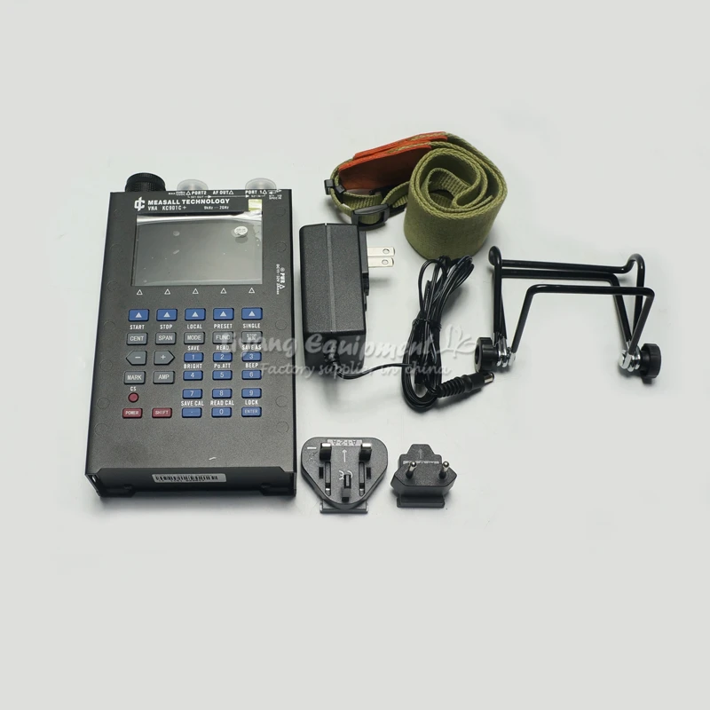
What in package
•1 x KC901V
•1 x power adapter
•1 x strap
•1 x user manual
•1 x desktop stand
Package Size
≈ 31cm×26cm×12cm
≈ 2.0Kg
Warranty and Return
1 year warranty
30 days return (Only quality problems)
Shipping with DHL/TNT/FedEX.
The model KC901M
KC901M 9.8GHz Handheld Network Analyzer RF multimeter
Description
KC901M is a multipurpose RF instrument integrating a VNA (vector network analyzer), spectrum analyzer, field strength meter, and an extra low-frequency signal source. It can do complete single port vector measurement and 2-ports simple vector network analyzing.
Main Features
•Vector network analyzing up to 10GHz
•1Hz frequency step
•Good accuracy and anti-interference ability
•Abundant functions and easy to carry (Weight less than 1kg)
Main Functions
•Transmission measurement (Filter adjustments, measuring amplifiers, verifying directivity of antennas)
•Reflection measurement (Impedance matching network adjustment, antenna feeding system quality evaluation)
•RF source plus an extra audio signal source
•Spectrum display and field strength observation (potentially used for inspecting a radio station's emission performance, or for searching for the interference sources)
Recommended Applications
•KC901V is mainly used for adjusting various RF circuits, such as filters, amplifiers, splitters, combiners; testing input/output impedance, evaluating antenna feeding system and detecting equipment's signal amplitudes at all level. It can also do filed strength measurement, which is useful during miscellaneous kinds of search for interference source etc.
•Combining intelligence in the community, KC901V is the tool to study RF for students and hobbies. In professional situations, it is used in communication engineering, antenna manufacturing, daily maintenance of broadcast, RF circuits development and so on. KC901V improves working efficiency, ease the weight burden and improve working quality.
What in package
•1 x KC901V
•1 x power adapter
•1 x strap
•1 x user manual
•1 x desktop stand
Package Size
≈ 31cm×26cm×12cm
≈ 2.0Kg
Warranty and Return
1 year warranty
30 days return (Only quality problems)
Shipping with DHL/TNT/FedEX.
![]()
![]()
![]()
![]()
![]()
![]()
![]()
![]()
![]() The model KC901V
KC901V vector network antenna feeder tester spectrum field strength signal source standing wave meter
The KC901V is a versatile RF multimeter whose main function is the single port vector network analyzer (VNA, S11). It supports vector transmission test (S21 scalar and simple vector), simple spectrum analyzer, field strength meter, RF signal source, Audio signal source and other functions. KC901V has a professional practicality, and includes support for 4 hours of continuous work, including the battery, the volume of only 1 cbm, weighs only 1 kg, to bring users a new free experience.
◆ Main functions
Transmission test (scalar: debug filter, amplifier, check antenna directivity, vector: basic phase change trend)
Reflectance Test (Vector: Debug impedance matching, check the quality of the antenna feed system)
Spectrum display and field strength observation *** (test station radio performance, find the source of interference)
The signal of a certain frequency point is output separately
◆ Recommended Applications
KC901V is mainly used for detecting and debugging RF circuit and antenna feeder system. In most frequency bands, can also be field strength measurement, interference search and so on.
This instrument is lightweight and powerful, able to previously through a large laboratory equipment to complete the measurement work easily transferred to the scene. 901V is an electronic engineer worthy of the test tools, but also as a professional communications engineering, radio and television launch pad technical staff standing equipment.
◆ Specifications (for reference only)
project
Test Conditions
parameter
Remarks
lowest
typical
highest
Frequency range is valid
9KHz
6.8 GHz
SPEC mode can be set
Lt; / RTI & gt;
7 GHz
Scanning Range
1 kHz
6.8 GHz
Number of scanning points
450pt
3150pt
Local operation
Frequency resolution All scanning class function 1Hz spectrum analyzer
All single frequency function 0.1Hz signal source and so on
Level resolution of 0.01dB
Phase resolution of 0.01 °
The scanning speed RBW = 30KHz, every point 1.2ms
RBW = 10 kHz, 1.5 ms per point
RBW = 3 kHz, 2 ms per point
RBW = 1 kHz, 3 ms per point
RBW = 30K, 450pt each screen 0.5s
Output level 1MHz-5GHz -10dBm 0dBm 6dBm 1 port
1MHz-5GHz 0dBm 6dBm 10dBm 2 ports
5 GHz - 6.8 GHz - 20 dBm 0 dBm 1 port
5 GHz - 6.8 GHz - 10 dBm 6 dBm 2 ports
Output attenuation 0dB 25dB
55dB 2 ports
1 port
Sensitivity 1MHz-5GHz -107dBm 1 port RBW = 1KHz
5 GHz to 6.8 GHz to 94 dBm
Available dynamic range for transmission measurements 1MHz to 500MHz 100dB Equivalent to the transmit and receive channel isolation
500MHz-2GHz 70dB
2GHz-6.8GHz 50dB
Transmission Measurement Uncertainty in Series 10dB Attenuator After Pass-Through Calibration, 0.3 + 0.05L at Insertion Loss <40dB
Insertion of the zero-drift compensation of the existing insertion loss L <30dB 0.05dB preheat 5min, every 5 minutes
The absolute orientation of the bridge 9kHz-1MHz 18dB 90% confidence interval
1MHz-6.8GHz 20dB
S11 relative directional 9kHz-3GHz 45dB after calibration, 90% confidence interval
3GHz-6GHz 40dB
6GHz-6.8GHz 35dB
Uncertainty of return loss After pass-through calibration, 1.0 + 0.1RL when 3dB <RL <25dB
Phase uncertainty 100kHz-1GHz 2 ° reflection coefficient ρ> 0.25
1 GHz to 3 GHz
3GHz-6.8GHz 8 [deg.]
project
Test Conditions
parameter
Remarks
lowest
typical
highest
Port VSWR port 2,1MHz-6GHz 1.5 Static value
Port 1,1 MHz-6 GHz 2.0
Local oscillator leakage port 1 -60dBm
-10dBm
IF feed-through rejection is 30dB
Frequency stability, per year
1 ppm
Power supply voltage charging interface
11V
32V
AC power adapter
105V
230V
Built-in battery
6.5V
8.4V
Temperature range for normal use
0 & gt; C
45 ° C
Note 2
Allowed
-40 ° C
65 ° C
Humidity range of continuous power-on state 0%
95%
Note 3
Damage level
All ports DC15V, +20 dBm
Dimensions
200 × 114 × 46mm (length × width × thickness)
Quality host (including battery) 1.2kg
Standard configuration of the entire package 2.0kg
Note 1: Unless otherwise noted, the specifications are measured at medium speed mode with an analysis bandwidth (RBW) of 10 kHz, an output attenuation of 0, a temperature of 25 ° C and a user calibration. A small number of accidental or permanent abnormal data segments may be outside the scope of the specification.
Note 2: The battery temperature range depends on the battery temperature characteristics. In the range of more than 0 ... 45 ℃, the device should be re-calibrated after the preheat stability. Especially in the -40 ... -20 ℃ range, should be at least 5 minutes of preheating (and the need to keep running). Due to the heat of the device itself, the shell temperature may be higher than the ambient temperature of 20 ℃, more than 45 ℃ in the environment, should avoid burns. When used in an environment close to 65 ° C, the battery must be removed, otherwise the battery temperature may exceed 85 ° C and cause danger.
Note 3: Use only. In the humidity above 80% of the local long-term storage, must be moisture-proof measures.
Weight:2.5KG
The model KC901V
KC901V vector network antenna feeder tester spectrum field strength signal source standing wave meter
The KC901V is a versatile RF multimeter whose main function is the single port vector network analyzer (VNA, S11). It supports vector transmission test (S21 scalar and simple vector), simple spectrum analyzer, field strength meter, RF signal source, Audio signal source and other functions. KC901V has a professional practicality, and includes support for 4 hours of continuous work, including the battery, the volume of only 1 cbm, weighs only 1 kg, to bring users a new free experience.
◆ Main functions
Transmission test (scalar: debug filter, amplifier, check antenna directivity, vector: basic phase change trend)
Reflectance Test (Vector: Debug impedance matching, check the quality of the antenna feed system)
Spectrum display and field strength observation *** (test station radio performance, find the source of interference)
The signal of a certain frequency point is output separately
◆ Recommended Applications
KC901V is mainly used for detecting and debugging RF circuit and antenna feeder system. In most frequency bands, can also be field strength measurement, interference search and so on.
This instrument is lightweight and powerful, able to previously through a large laboratory equipment to complete the measurement work easily transferred to the scene. 901V is an electronic engineer worthy of the test tools, but also as a professional communications engineering, radio and television launch pad technical staff standing equipment.
◆ Specifications (for reference only)
project
Test Conditions
parameter
Remarks
lowest
typical
highest
Frequency range is valid
9KHz
6.8 GHz
SPEC mode can be set
Lt; / RTI & gt;
7 GHz
Scanning Range
1 kHz
6.8 GHz
Number of scanning points
450pt
3150pt
Local operation
Frequency resolution All scanning class function 1Hz spectrum analyzer
All single frequency function 0.1Hz signal source and so on
Level resolution of 0.01dB
Phase resolution of 0.01 °
The scanning speed RBW = 30KHz, every point 1.2ms
RBW = 10 kHz, 1.5 ms per point
RBW = 3 kHz, 2 ms per point
RBW = 1 kHz, 3 ms per point
RBW = 30K, 450pt each screen 0.5s
Output level 1MHz-5GHz -10dBm 0dBm 6dBm 1 port
1MHz-5GHz 0dBm 6dBm 10dBm 2 ports
5 GHz - 6.8 GHz - 20 dBm 0 dBm 1 port
5 GHz - 6.8 GHz - 10 dBm 6 dBm 2 ports
Output attenuation 0dB 25dB
55dB 2 ports
1 port
Sensitivity 1MHz-5GHz -107dBm 1 port RBW = 1KHz
5 GHz to 6.8 GHz to 94 dBm
Available dynamic range for transmission measurements 1MHz to 500MHz 100dB Equivalent to the transmit and receive channel isolation
500MHz-2GHz 70dB
2GHz-6.8GHz 50dB
Transmission Measurement Uncertainty in Series 10dB Attenuator After Pass-Through Calibration, 0.3 + 0.05L at Insertion Loss <40dB
Insertion of the zero-drift compensation of the existing insertion loss L <30dB 0.05dB preheat 5min, every 5 minutes
The absolute orientation of the bridge 9kHz-1MHz 18dB 90% confidence interval
1MHz-6.8GHz 20dB
S11 relative directional 9kHz-3GHz 45dB after calibration, 90% confidence interval
3GHz-6GHz 40dB
6GHz-6.8GHz 35dB
Uncertainty of return loss After pass-through calibration, 1.0 + 0.1RL when 3dB <RL <25dB
Phase uncertainty 100kHz-1GHz 2 ° reflection coefficient ρ> 0.25
1 GHz to 3 GHz
3GHz-6.8GHz 8 [deg.]
project
Test Conditions
parameter
Remarks
lowest
typical
highest
Port VSWR port 2,1MHz-6GHz 1.5 Static value
Port 1,1 MHz-6 GHz 2.0
Local oscillator leakage port 1 -60dBm
-10dBm
IF feed-through rejection is 30dB
Frequency stability, per year
1 ppm
Power supply voltage charging interface
11V
32V
AC power adapter
105V
230V
Built-in battery
6.5V
8.4V
Temperature range for normal use
0 & gt; C
45 ° C
Note 2
Allowed
-40 ° C
65 ° C
Humidity range of continuous power-on state 0%
95%
Note 3
Damage level
All ports DC15V, +20 dBm
Dimensions
200 × 114 × 46mm (length × width × thickness)
Quality host (including battery) 1.2kg
Standard configuration of the entire package 2.0kg
Note 1: Unless otherwise noted, the specifications are measured at medium speed mode with an analysis bandwidth (RBW) of 10 kHz, an output attenuation of 0, a temperature of 25 ° C and a user calibration. A small number of accidental or permanent abnormal data segments may be outside the scope of the specification.
Note 2: The battery temperature range depends on the battery temperature characteristics. In the range of more than 0 ... 45 ℃, the device should be re-calibrated after the preheat stability. Especially in the -40 ... -20 ℃ range, should be at least 5 minutes of preheating (and the need to keep running). Due to the heat of the device itself, the shell temperature may be higher than the ambient temperature of 20 ℃, more than 45 ℃ in the environment, should avoid burns. When used in an environment close to 65 ° C, the battery must be removed, otherwise the battery temperature may exceed 85 ° C and cause danger.
Note 3: Use only. In the humidity above 80% of the local long-term storage, must be moisture-proof measures.
Weight:2.5KG
![]()
![]()
![]()
![]()
![]()
![]()
![]()
![]()
![]()
![]() The model KC901S+
The model KC901S+
![]()
![]()
![]()
![]()
![]()
![]()
![]()
![]()
![]()
![]()
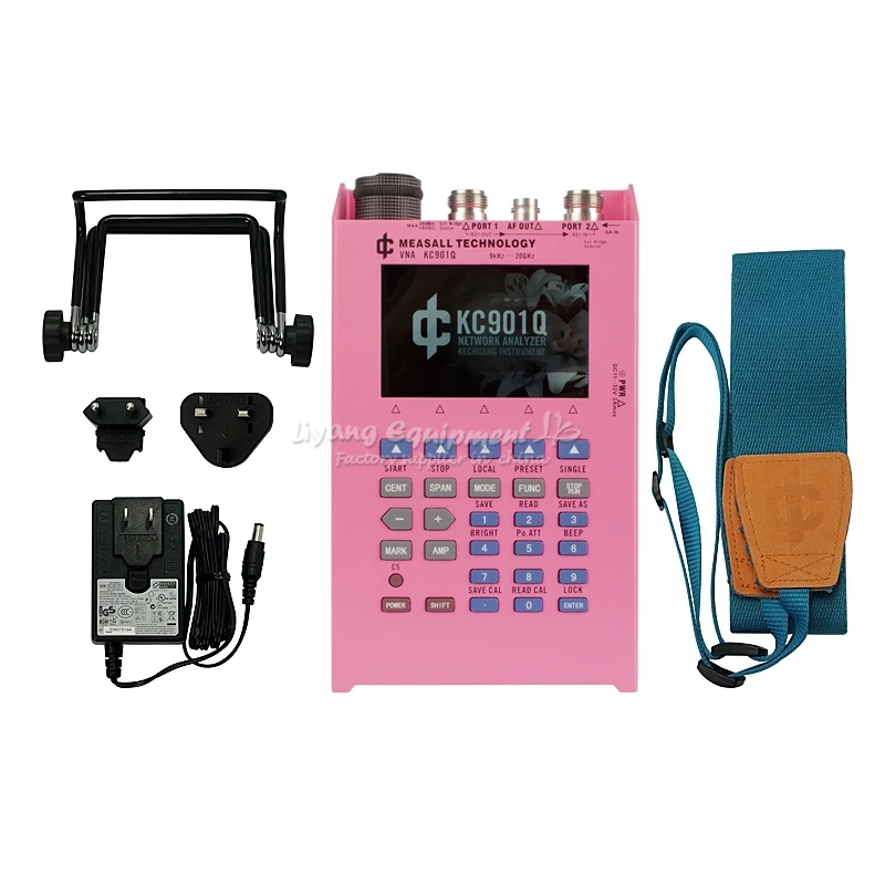
The model KC901Q
The KC901Q is a vector sweeper. He is able to measure the amplitude and phase changes that occur after the signal passes through the device, while extending the spectrum, field strength, and signal generator functions, adding practicality to form a RF multimeter. The KC901Q uses the basic architecture of the KC901x. However, the KC901Q does not have a built-in bridge. The basic function is the sweeper (providing amplitude and phase), which is significantly different from other instruments in the KC901 series. The KC901Q can perform vector reflection measurements with an external bridge or directional coupler. The instrument has a built-in full-port calibration model that supports OSL calibration. Sweep measurements support response calibration (amplitude and phase). ◆Main Features* 30GHz frequency range 1Hz frequency stepping Good accuracy and stability Double frequency conversion, strong anti-interference ability Rich in function and easy to carry ◆Main function Sweep test (get amplitude difference, phase difference) Reflection test (external directional coupler required) Low frequency and RF signal sources** Spectrum display and field strength observation** ◆Recommended application The KC901Q is mainly used to debug various RF circuits, such as filters, amplifiers, splitters, combiners, external directional couplers or standing wave bridges, to test the input and output impedance, and to evaluate the quality of the antenna system. With its receiver, it can also detect the signal amplitude of each level of the equipment, and perform field strength measurement and interference search in some frequency bands. KC901Q is a good tool for learning RF knowledge. In the professional field, it can be used in the fields of communication engineering, antenna manufacturing, and routine maintenance such as radar, microwave stations, satellite earth stations, and radio astronomy stations. The following scenarios may not apply: The spectrum and field strength functions are not suitable for measuring pulse and wideband signals (eg radar, WIFI, Bluetooth), frequency hopping signals. In some cases, qualitative observations can be completed by experienced engineers, but we cannot guarantee that every user can complete it. Any test should not have strong interfering signals in the 109-110MHz range. Some broadcast transmitting stations have 109MHz spurs. If the antenna is measured near the transmitting station, it will affect the accuracy of the instrument. * Please read the technical manual ** Informal features ◆Working principle The basic principle of the KC901Q is similar to other products in the KC901x family, but it does not have a built-in bridge. The basic principle of the instrument is that the RF signal source produces a measurement signal, which is sampled from the instrument 1 port after being sampled by the forward splitter. After the measurement signal passes through the device under test, it is input from the instrument 2 port, detected by the receiver, and compared with the signal sample obtained from the 1 port. The signal source is divided into three frequency bands: signals below 60MHz are generated by a direct digital synthesizer (DDS); signals above 60MHz and below 7GHz are generated by a phase-locked loop frequency synthesizer (PLL) and passed through an attenuator; The signal is multiplied and does not pass through the attenuator. The signals of the three frequency bands are gated through the RF switch and combined into one RF signal output. The figure below is a block diagram of the KC901Q. The machine has two phase-locked loop frequency synthesizers with frequency dividers covering the range of 60MHz-15GHz. The circuit can work normally to 26.5 GHz until 30 GHz still has a weak output, but above 24 GHz, the indicator has rapidly deteriorated. There are two receivers inside the instrument, and the local oscillator is provided by the same phase-locked loop frequency synthesizer. One of the receivers detects the output signal of port 1 through the internal circuitry of the instrument. The other receiver is connected to port 2 to detect external inputs. By comparing the amplitude and phase of the two receivers, the amplitude difference and phase difference between Port 1 and Port 2 can be obtained. The instrument uses 7GHz as the breakpoint. Below 7GHz, the signal does not pass through the frequency multiplier and is output through the adjustable attenuator. The PLL outputs a signal of 3.5 GHz to 15 GHz, and a signal of 7-30 GHz is obtained by a frequency multiplier. Since the adjustable attenuator supporting 30 GHz is slightly more expensive, the application requirements of the integrated trade-off products have no built-in attenuators at frequencies above 7 GHz. KC901Q uses secondary frequency conversion, the first intermediate frequency is 109.65MHz, and the second intermediate frequency is 350KHz. The second intermediate frequency is digitized by the synchronous sampling ADC and sent to the FPGA for subsequent digital processing. The DDS in the machine can be directly output to form an audio signal source. Since the KC901Q does not have a built-in bridge, an external directional device is required to measure the reflection parameters. An equal arm or unequal arm Wheatstone bridge can be used in the lower frequency band, and a directional coupler is preferred in the higher frequency band. Directional couplers can be made or purchased based on common frequency ranges. This type of coupler is inexpensive and reduces the cost of the package. The connection between the directional coupler and the instrument should be as short as possible, preferably with a semi-steel wire connection of no more than 20 cm in length. The KC901Q does not have S11 factory calibration data due to the absence of a built-in bridge. After the external directional bridge is attached, calibration must be performed. If a bridge or coupler is often used, system calibration can be done for them for future use. If it is only a temporary measure, only user calibration can be performed. A disadvantage of user calibration is that once the frequency is changed, the calibration fails. ◆Technical specifications The basic technical specifications of the 901Q are as follows (the products may be slightly different in different periods): project Test Conditions parameter Remarks lowest typical highest Frequency Range Spectrum/transmission Effective 9kHz 20GHz Settable 0 30GHz Frequency Range (reflection) Effective Depending on the external orientation device in the 5kHz-20GHz range Settable 5kHz 30GHz Scanning range SPAN 1KHz 29.99GHz Scan points 450pt 3150pt Local operation Frequency resolution All scanning functions 1Hz Low frequency signal source 0.1Hz Level resolution 0.01dB Phase resolution 0.01° Scanning speed RBW=30KHz, every point 1.2ms RBW=10KHz, every point 1.5ms RBW=3KHz, every point 2.4ms RBW=1KHz, every point 4ms RBW=30K, 450pt per screen 0.6s Output level Scan mode 1MHz-7GHz -10dBm 6dBm 10dBm 7GHz-20GHz -13dBm 0dBm 6dBm 20GHz-26GHz -20dBm -13dBm -6dBm No guarantee Maximum output level 1MHz-7GHz signal source 3dBm 10dBm 13dBm 7GHz-20GHz signal source -13dBm 0dBm 6dBm Output attenuation 9kHz-7GHz 0dB 25dB Note 2 Sensitivity 1MHz-7GHz -101dBm -107dBm -113dBm Port 2 RBW=1KHz 7GHz-15GHz -98dBm -104dBm -110dBm 15GHz-22GHz -95dBm -101dBm The available dynamic range of the transmission measurement 1MHz-1GHz 95dB 100dB Equivalent to transceiver channel isolation Note 3 1GHz-2GHz 85dB 90dB 2GHz-15GHz 70dB 15GHz-24GHz 60dB 24GHz-26.5GHz 40dB Amplitude uncertainty of transmission measurement 1MHz-20GHz After straight-through calibration, when the insertion loss is L<40dB 0.5+0.1L Note 4 Zero offset drift of insertion loss When the existing insertion loss of compensation is L<30dB, 1MHz-15GHz 0.1dB Preheated for 5 minutes Directional device directivity is better than 15dB, directionality after calibration 9kHz-7GHz 45dB An external orientation device is required. 7GHz-15GHz 40dB 15GHz-20GHz 35dB 20GHz-26GHz 25dB


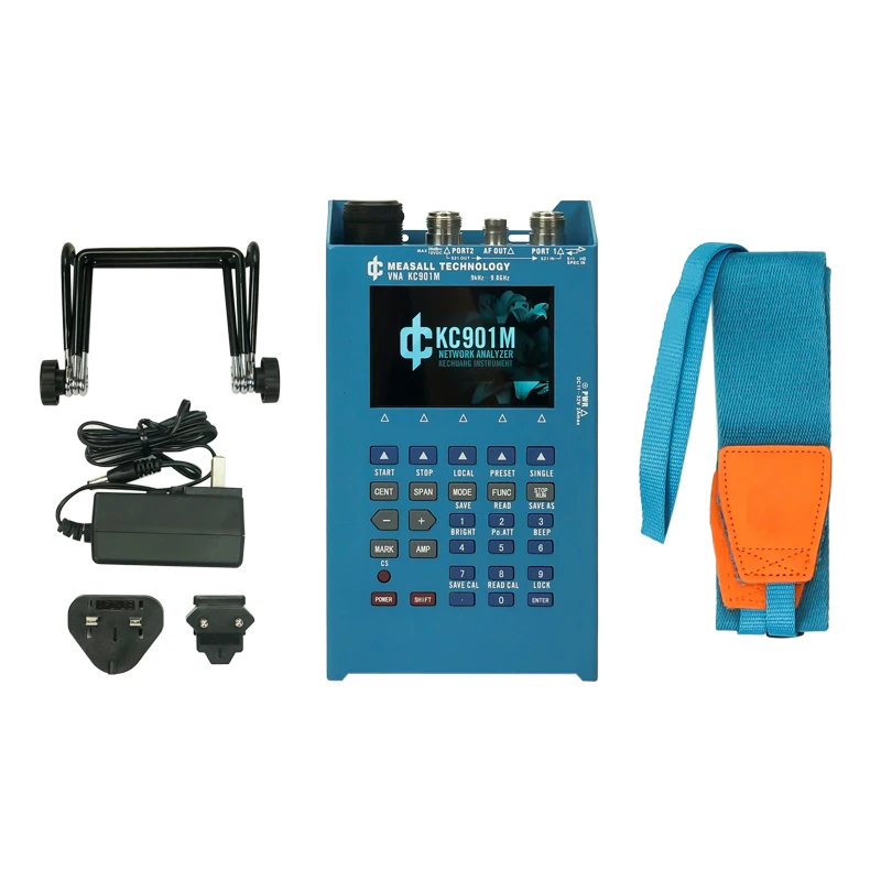
 The model KC901M
KC901M 9.8GHz Handheld Network Analyzer RF multimeter
Description
KC901M is a multipurpose RF instrument integrating a VNA (vector network analyzer), spectrum analyzer, field strength meter, and an extra low-frequency signal source. It can do complete single port vector measurement and 2-ports simple vector network analyzing.
Main Features
•Vector network analyzing up to 10GHz
•1Hz frequency step
•Good accuracy and anti-interference ability
•Abundant functions and easy to carry (Weight less than 1kg)
Main Functions
•Transmission measurement (Filter adjustments, measuring amplifiers, verifying directivity of antennas)
•Reflection measurement (Impedance matching network adjustment, antenna feeding system quality evaluation)
•RF source plus an extra audio signal source
•Spectrum display and field strength observation (potentially used for inspecting a radio station's emission performance, or for searching for the interference sources)
Recommended Applications
•KC901V is mainly used for adjusting various RF circuits, such as filters, amplifiers, splitters, combiners; testing input/output impedance, evaluating antenna feeding system and detecting equipment's signal amplitudes at all level. It can also do filed strength measurement, which is useful during miscellaneous kinds of search for interference source etc.
•Combining intelligence in the community, KC901V is the tool to study RF for students and hobbies. In professional situations, it is used in communication engineering, antenna manufacturing, daily maintenance of broadcast, RF circuits development and so on. KC901V improves working efficiency, ease the weight burden and improve working quality.
What in package
•1 x KC901V
•1 x power adapter
•1 x strap
•1 x user manual
•1 x desktop stand
Package Size
≈ 31cm×26cm×12cm
≈ 2.0Kg
Warranty and Return
1 year warranty
30 days return (Only quality problems)
Shipping with DHL/TNT/FedEX.
The model KC901M
KC901M 9.8GHz Handheld Network Analyzer RF multimeter
Description
KC901M is a multipurpose RF instrument integrating a VNA (vector network analyzer), spectrum analyzer, field strength meter, and an extra low-frequency signal source. It can do complete single port vector measurement and 2-ports simple vector network analyzing.
Main Features
•Vector network analyzing up to 10GHz
•1Hz frequency step
•Good accuracy and anti-interference ability
•Abundant functions and easy to carry (Weight less than 1kg)
Main Functions
•Transmission measurement (Filter adjustments, measuring amplifiers, verifying directivity of antennas)
•Reflection measurement (Impedance matching network adjustment, antenna feeding system quality evaluation)
•RF source plus an extra audio signal source
•Spectrum display and field strength observation (potentially used for inspecting a radio station's emission performance, or for searching for the interference sources)
Recommended Applications
•KC901V is mainly used for adjusting various RF circuits, such as filters, amplifiers, splitters, combiners; testing input/output impedance, evaluating antenna feeding system and detecting equipment's signal amplitudes at all level. It can also do filed strength measurement, which is useful during miscellaneous kinds of search for interference source etc.
•Combining intelligence in the community, KC901V is the tool to study RF for students and hobbies. In professional situations, it is used in communication engineering, antenna manufacturing, daily maintenance of broadcast, RF circuits development and so on. KC901V improves working efficiency, ease the weight burden and improve working quality.
What in package
•1 x KC901V
•1 x power adapter
•1 x strap
•1 x user manual
•1 x desktop stand
Package Size
≈ 31cm×26cm×12cm
≈ 2.0Kg
Warranty and Return
1 year warranty
30 days return (Only quality problems)
Shipping with DHL/TNT/FedEX.


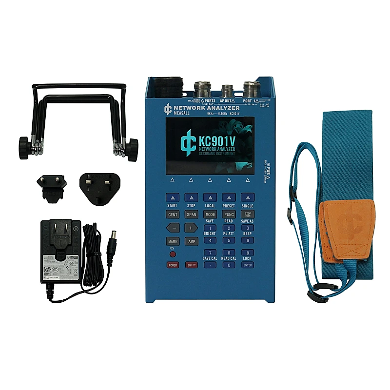
 The model KC901V
KC901V vector network antenna feeder tester spectrum field strength signal source standing wave meter
The KC901V is a versatile RF multimeter whose main function is the single port vector network analyzer (VNA, S11). It supports vector transmission test (S21 scalar and simple vector), simple spectrum analyzer, field strength meter, RF signal source, Audio signal source and other functions. KC901V has a professional practicality, and includes support for 4 hours of continuous work, including the battery, the volume of only 1 cbm, weighs only 1 kg, to bring users a new free experience.
◆ Main functions
Transmission test (scalar: debug filter, amplifier, check antenna directivity, vector: basic phase change trend)
Reflectance Test (Vector: Debug impedance matching, check the quality of the antenna feed system)
Spectrum display and field strength observation *** (test station radio performance, find the source of interference)
The signal of a certain frequency point is output separately
◆ Recommended Applications
KC901V is mainly used for detecting and debugging RF circuit and antenna feeder system. In most frequency bands, can also be field strength measurement, interference search and so on.
This instrument is lightweight and powerful, able to previously through a large laboratory equipment to complete the measurement work easily transferred to the scene. 901V is an electronic engineer worthy of the test tools, but also as a professional communications engineering, radio and television launch pad technical staff standing equipment.
◆ Specifications (for reference only)
project
Test Conditions
parameter
Remarks
lowest
typical
highest
Frequency range is valid
9KHz
6.8 GHz
SPEC mode can be set
Lt; / RTI & gt;
7 GHz
Scanning Range
1 kHz
6.8 GHz
Number of scanning points
450pt
3150pt
Local operation
Frequency resolution All scanning class function 1Hz spectrum analyzer
All single frequency function 0.1Hz signal source and so on
Level resolution of 0.01dB
Phase resolution of 0.01 °
The scanning speed RBW = 30KHz, every point 1.2ms
RBW = 10 kHz, 1.5 ms per point
RBW = 3 kHz, 2 ms per point
RBW = 1 kHz, 3 ms per point
RBW = 30K, 450pt each screen 0.5s
Output level 1MHz-5GHz -10dBm 0dBm 6dBm 1 port
1MHz-5GHz 0dBm 6dBm 10dBm 2 ports
5 GHz - 6.8 GHz - 20 dBm 0 dBm 1 port
5 GHz - 6.8 GHz - 10 dBm 6 dBm 2 ports
Output attenuation 0dB 25dB
55dB 2 ports
1 port
Sensitivity 1MHz-5GHz -107dBm 1 port RBW = 1KHz
5 GHz to 6.8 GHz to 94 dBm
Available dynamic range for transmission measurements 1MHz to 500MHz 100dB Equivalent to the transmit and receive channel isolation
500MHz-2GHz 70dB
2GHz-6.8GHz 50dB
Transmission Measurement Uncertainty in Series 10dB Attenuator After Pass-Through Calibration, 0.3 + 0.05L at Insertion Loss <40dB
Insertion of the zero-drift compensation of the existing insertion loss L <30dB 0.05dB preheat 5min, every 5 minutes
The absolute orientation of the bridge 9kHz-1MHz 18dB 90% confidence interval
1MHz-6.8GHz 20dB
S11 relative directional 9kHz-3GHz 45dB after calibration, 90% confidence interval
3GHz-6GHz 40dB
6GHz-6.8GHz 35dB
Uncertainty of return loss After pass-through calibration, 1.0 + 0.1RL when 3dB <RL <25dB
Phase uncertainty 100kHz-1GHz 2 ° reflection coefficient ρ> 0.25
1 GHz to 3 GHz
3GHz-6.8GHz 8 [deg.]
project
Test Conditions
parameter
Remarks
lowest
typical
highest
Port VSWR port 2,1MHz-6GHz 1.5 Static value
Port 1,1 MHz-6 GHz 2.0
Local oscillator leakage port 1 -60dBm
-10dBm
IF feed-through rejection is 30dB
Frequency stability, per year
1 ppm
Power supply voltage charging interface
11V
32V
AC power adapter
105V
230V
Built-in battery
6.5V
8.4V
Temperature range for normal use
0 & gt; C
45 ° C
Note 2
Allowed
-40 ° C
65 ° C
Humidity range of continuous power-on state 0%
95%
Note 3
Damage level
All ports DC15V, +20 dBm
Dimensions
200 × 114 × 46mm (length × width × thickness)
Quality host (including battery) 1.2kg
Standard configuration of the entire package 2.0kg
Note 1: Unless otherwise noted, the specifications are measured at medium speed mode with an analysis bandwidth (RBW) of 10 kHz, an output attenuation of 0, a temperature of 25 ° C and a user calibration. A small number of accidental or permanent abnormal data segments may be outside the scope of the specification.
Note 2: The battery temperature range depends on the battery temperature characteristics. In the range of more than 0 ... 45 ℃, the device should be re-calibrated after the preheat stability. Especially in the -40 ... -20 ℃ range, should be at least 5 minutes of preheating (and the need to keep running). Due to the heat of the device itself, the shell temperature may be higher than the ambient temperature of 20 ℃, more than 45 ℃ in the environment, should avoid burns. When used in an environment close to 65 ° C, the battery must be removed, otherwise the battery temperature may exceed 85 ° C and cause danger.
Note 3: Use only. In the humidity above 80% of the local long-term storage, must be moisture-proof measures.
Weight:2.5KG
The model KC901V
KC901V vector network antenna feeder tester spectrum field strength signal source standing wave meter
The KC901V is a versatile RF multimeter whose main function is the single port vector network analyzer (VNA, S11). It supports vector transmission test (S21 scalar and simple vector), simple spectrum analyzer, field strength meter, RF signal source, Audio signal source and other functions. KC901V has a professional practicality, and includes support for 4 hours of continuous work, including the battery, the volume of only 1 cbm, weighs only 1 kg, to bring users a new free experience.
◆ Main functions
Transmission test (scalar: debug filter, amplifier, check antenna directivity, vector: basic phase change trend)
Reflectance Test (Vector: Debug impedance matching, check the quality of the antenna feed system)
Spectrum display and field strength observation *** (test station radio performance, find the source of interference)
The signal of a certain frequency point is output separately
◆ Recommended Applications
KC901V is mainly used for detecting and debugging RF circuit and antenna feeder system. In most frequency bands, can also be field strength measurement, interference search and so on.
This instrument is lightweight and powerful, able to previously through a large laboratory equipment to complete the measurement work easily transferred to the scene. 901V is an electronic engineer worthy of the test tools, but also as a professional communications engineering, radio and television launch pad technical staff standing equipment.
◆ Specifications (for reference only)
project
Test Conditions
parameter
Remarks
lowest
typical
highest
Frequency range is valid
9KHz
6.8 GHz
SPEC mode can be set
Lt; / RTI & gt;
7 GHz
Scanning Range
1 kHz
6.8 GHz
Number of scanning points
450pt
3150pt
Local operation
Frequency resolution All scanning class function 1Hz spectrum analyzer
All single frequency function 0.1Hz signal source and so on
Level resolution of 0.01dB
Phase resolution of 0.01 °
The scanning speed RBW = 30KHz, every point 1.2ms
RBW = 10 kHz, 1.5 ms per point
RBW = 3 kHz, 2 ms per point
RBW = 1 kHz, 3 ms per point
RBW = 30K, 450pt each screen 0.5s
Output level 1MHz-5GHz -10dBm 0dBm 6dBm 1 port
1MHz-5GHz 0dBm 6dBm 10dBm 2 ports
5 GHz - 6.8 GHz - 20 dBm 0 dBm 1 port
5 GHz - 6.8 GHz - 10 dBm 6 dBm 2 ports
Output attenuation 0dB 25dB
55dB 2 ports
1 port
Sensitivity 1MHz-5GHz -107dBm 1 port RBW = 1KHz
5 GHz to 6.8 GHz to 94 dBm
Available dynamic range for transmission measurements 1MHz to 500MHz 100dB Equivalent to the transmit and receive channel isolation
500MHz-2GHz 70dB
2GHz-6.8GHz 50dB
Transmission Measurement Uncertainty in Series 10dB Attenuator After Pass-Through Calibration, 0.3 + 0.05L at Insertion Loss <40dB
Insertion of the zero-drift compensation of the existing insertion loss L <30dB 0.05dB preheat 5min, every 5 minutes
The absolute orientation of the bridge 9kHz-1MHz 18dB 90% confidence interval
1MHz-6.8GHz 20dB
S11 relative directional 9kHz-3GHz 45dB after calibration, 90% confidence interval
3GHz-6GHz 40dB
6GHz-6.8GHz 35dB
Uncertainty of return loss After pass-through calibration, 1.0 + 0.1RL when 3dB <RL <25dB
Phase uncertainty 100kHz-1GHz 2 ° reflection coefficient ρ> 0.25
1 GHz to 3 GHz
3GHz-6.8GHz 8 [deg.]
project
Test Conditions
parameter
Remarks
lowest
typical
highest
Port VSWR port 2,1MHz-6GHz 1.5 Static value
Port 1,1 MHz-6 GHz 2.0
Local oscillator leakage port 1 -60dBm
-10dBm
IF feed-through rejection is 30dB
Frequency stability, per year
1 ppm
Power supply voltage charging interface
11V
32V
AC power adapter
105V
230V
Built-in battery
6.5V
8.4V
Temperature range for normal use
0 & gt; C
45 ° C
Note 2
Allowed
-40 ° C
65 ° C
Humidity range of continuous power-on state 0%
95%
Note 3
Damage level
All ports DC15V, +20 dBm
Dimensions
200 × 114 × 46mm (length × width × thickness)
Quality host (including battery) 1.2kg
Standard configuration of the entire package 2.0kg
Note 1: Unless otherwise noted, the specifications are measured at medium speed mode with an analysis bandwidth (RBW) of 10 kHz, an output attenuation of 0, a temperature of 25 ° C and a user calibration. A small number of accidental or permanent abnormal data segments may be outside the scope of the specification.
Note 2: The battery temperature range depends on the battery temperature characteristics. In the range of more than 0 ... 45 ℃, the device should be re-calibrated after the preheat stability. Especially in the -40 ... -20 ℃ range, should be at least 5 minutes of preheating (and the need to keep running). Due to the heat of the device itself, the shell temperature may be higher than the ambient temperature of 20 ℃, more than 45 ℃ in the environment, should avoid burns. When used in an environment close to 65 ° C, the battery must be removed, otherwise the battery temperature may exceed 85 ° C and cause danger.
Note 3: Use only. In the humidity above 80% of the local long-term storage, must be moisture-proof measures.
Weight:2.5KG


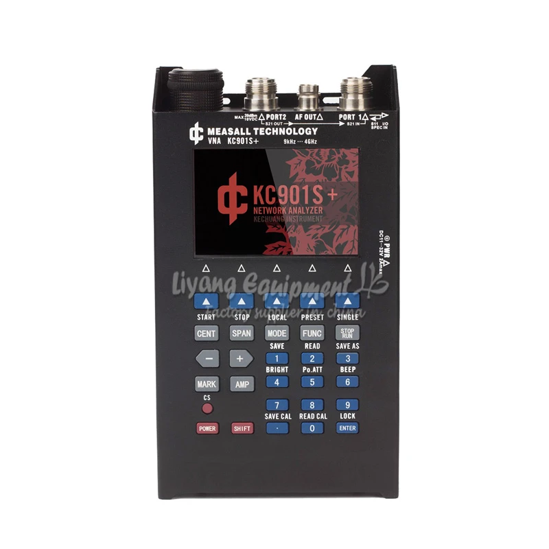
 The model KC901S+
KC901S+ vector network tester spectrum RF analyzer SWR 4G standing wave test meter
Including vector reflection, scalar transmission, spectrum, signal source and other functions, to resolve common radio frequency testing. Applicable in communications engineering, radio and television engineering, radio enthusiasts, research and education and other fields
901S+ is an upgraded version of 901S, the frequencies is up to 4G.
KC901S+ is a universal vector antenna analyzer. It supports the analysis of single port vector network analysis and dual port scalar network analysis, meanwhile expanding the spectrum, field strength and signal generator convenient function. KC901S+ has professional practicality, and includes the battery which supports 5 hours large work load, the volume is just 1 dm3, weight is only 1 kg, bring a new experience for the user.
◆Main features*
9KHz-4GHzfrequency range
1Hz frequency resolution
Reliable accuracy and stability
Two frequency conversion, external interference resistance
Rich functionality and lightweight design
◆Main functions
Transmission test(scalar:debug filter,amplifier,test antenna directivity)
Reflection test(vector:regulate impedance matching, check the antenna system quality)
Spectrum display and field strength observation**(Test radio transmitter performance and find interference sources)
Output one frequency point signal individually
◆Suggesting application
KC901S+ is mainly used for debugging various RF circuits, such as filters, amplifiers, splitter, combiner, test input and output impedance, the quality evaluation of antenna system, signal amplitude detection of equipment at all levels. In most frequency bands, it also can measure field strength, and do interference search and other work.
This instrument can effectively improve work efficiency, reduce the carrying burden, improve the quality of work. 901S is a test tool for every electronic engineers, also as a regular instrument of professional communication engineering, and radio television transmitting station technical personnel.
◆The difference between 901S+ and 901S
901S+ is the upgraded product of 901S
901S+ adopts all digital intermediate frequency technology
901S+ the trace noise has improved more observably than 901
The electric bridge structure of 901S is improved, its nonlinear effect is smaller than 901S, and the accuracy of impedance test is improved
Based on the improvements of the electric bridge, the 901S+ can support low to 9KHz of S11 measurements, and the directionality is still good at this time
The spectrum function of 901S+ shares a port with the S11 function, and the port usage in the transmission test is the opposite of 901S
The S21 function of 901S+ is also vector, and the introduction of phase can provide more intuitive trend judgment
The frequency range of 901S+ is 9KHz - 4.1GHz.
901S+ analysis bandwidth (RBW) has four choices, respectively are 1KHz, 3KHz, 10KHz, 30KHz, spectrum function is stronger than 901S
◆Technical indicators (for reference only)
Items
Test condition
Parameter
Remarks
Minimum
In general
Maximum
Frequency range
effective
9KHz
4GHz
SPEC Mode can be set
0
4.1GHz
Scan range
SPAN
1KHz
4GHz
Scan point
450pt
3150pt
Native operation
Frequency resolution
All scan functions
1Hz
Spectrum analyzer, etc.
Audio signal source function
0.1Hz
Bisection resolution
0.01dB
Phase resolution
0.01°
Scan speed
RBW=30KHz,each point
1.2ms
RBW=10KHz,each point
1.5ms
RBW=3KHz,each point
2ms
RBW=1KHz,each point
3ms
RBW=30K,450pt each screen
0.5s
Output frequency
1MHz-2GHz
-10dBm
-3dBm
3dBm
1 port
1MHz-2GHz
0dBm
6dBm
13dBm
2 port
2GHz-4GHz
-16dBm
0dBm
1 port
2GHz-4GHz
-10dBm
10dBm
2 port
Output
attenuatoin
0dB
20dB
Sensitivity
1MHz-3GHz
-107dBm
1 port
RBW=1KHz
3GHz-4GHz
-97dBm
The dynamic range of transmission measurements
1MHz-2GHz
70dB
Equivalent to the isolation of the transmit receive channel
2GHz-4GHz
50dB
Amplitude uncertainty of transmission measurements
Through direct calibration, plug loss L<60dB
0.3+0.05L
Zero drift of insertion loss
Compensated existing insertion loss L<30dB
0.05dB
Absolute directivity of bridge
9kHz-1MHz
18dB
90% Interval trusted
1MHz-4GHz
20dB
Relative directionality of S11
9kHz-3GHz
45dB
After calibration, the 90% interval is believable
3GHz-4GHz
35dB
Uncertainty of return loss
After direct calibration,3dB<RL<25dB
1.5+0.1RL
Phase uncertainty
100kHz-1GHz
2°
Reflection coefficientρ>0.25
1GHz-3GHz
5°
3GHz-4GHz
8°
Items
Test condition
Parameter
Remarks
Minimum
In general
Maximum
VSWR
Port 2,1MHz-4GHz
1.5
Quiescent value
Port 1,1MHz-4GHz
2.0
Lo-leaking
Port 1
-60dBm
-10dBm
Intermediate frequency feed through system
30dB
Frequency stability per year
0.3ppm
1ppm
Voltage
Charge port
11V
32V
AC power adapter
105V
230V
Internal battery
6.5V
8.4V
TEMP range
In general
0℃
45℃
Note2
Allowed for use
-40℃
65℃
Humidity range
Continuous boot state
0%
95%
Note3
Damage level
All port DC15V,+20dBm
Size
200×114×46mm
Weight
Main machine(including battery)
1.2kg
The total package
2.0kg
Note1:Unless otherwise specified, all indicators are measured in the medium speed mode, 10KHz RBW, 0 output attenuation, temperature 25 ℃, and through the user calibration. A few accidental or abnormal data permanent period may exceed the range of technical parameters table.
Note2:When the battery is powered, the range depends on the temperature characteristics of the battery. It exceeds 0... 45℃ should be re calibrated when the equipment is preheated and stable. Especially within the range of -40~-20℃ , should be preheated for at least 5 minutes (and need to keep running). Due to heating of the equipment itself, the shell temperature may be 20℃ higher than the ambient temperature. In more than 45℃ environment, should avoid scalding. We must remove the battery when the environment temperature is closed to 65℃. Otherwise, the battery temperature may exceed 85 ℃ and cause danger.
Note3: Restricted to usage state only. Moisture storage measures must be adopted for long-term storage at a moisture level greater than 80%


Трекер стоимости
Отзывы покупателей
Новые отзывы о товарах

Ольга 18 Декабря 2021, 11:22 #
Хорошая клавиатура для ноутбука. Тихая, но вместе с тем достаточно отзывчивая и при нажатии чувствуется небольшое сопротивление. Клавиатура экстротонкая,но вместе... Читать отзыв полностью...

Андрей Петров 19 Декабря 2021, 20:32 #
Не раз заказывала мужу штаны, всё понравилось. Качество хорошее. Цена дешевле, чем у нас, в местных магазинах .Конечно, здесь желательно... Читать отзыв полностью...

Станислав 20 Декабря 2021, 07:26 #
Заказал себе данный телефон для подарка девушке. Телефон мне пришёл через неделю с дня оформления заказа и оплаты. Сам телефон... Читать отзыв полностью...
Станислав 20 Декабря 2021, 07:39 #
Заказал себе данный Power Bank. Пришёл он мне в течении двух недель от момента заказа. При получении был надёжно упакован... Читать отзыв полностью...
Станислав 19 Декабря 2021, 11:37 #
Заказал сыну данный рюкзак, он показался мне практичным. Доставка была достаточно долгая где-то четыре месяца. Сам товар удобный, много помещается... Читать отзыв полностью...

Тиана 20 Декабря 2021, 09:23 #
Второй раз заказываем с АлиЭкспресс, через этот сайт. Доставкой довольна,быстро и во время. На счёт халатов просто нет слов,заказали со... Читать отзыв полностью...

Заказал этот набор. Пришло быстро, я не ожидал такой скорости доставки. Впечатление положительное. Качество хорошее, белье не растягивается как бывает... Читать отзыв полностью...