


Analyze network vector tester handheld RF multimeter KC901Q 20GHz without built-in bridge sweeper sweep generator | Инструменты
Сохраните в закладки:


История цены
*История изменения цены! Указанная стоимость возможно, уже изменилось. Проверить текущую цену - >
| Месяц | Минимальная цена | Макс. стоимость | Цена |
|---|---|---|---|
| Sep-15-2025 | 0.95 руб. | 0.62 руб. | 0 руб. |
| Aug-15-2025 | 0.93 руб. | 0.64 руб. | 0 руб. |
| Jul-15-2025 | 0.29 руб. | 0.77 руб. | 0 руб. |
| Jun-15-2025 | 0.16 руб. | 0.72 руб. | 0 руб. |
| May-15-2025 | 0.71 руб. | 0.66 руб. | 0 руб. |
| Apr-15-2025 | 0.32 руб. | 0.61 руб. | 0 руб. |
| Mar-15-2025 | 0.9 руб. | 0.71 руб. | 0 руб. |
| Feb-15-2025 | 0.80 руб. | 0.37 руб. | 0 руб. |
| Jan-15-2025 | 0.9 руб. | 0.38 руб. | 0 руб. |
Новые товары

Аппарат для тестирования ЖК-экрана WOZNIAK DL S300 6 в 1 iPhone Samsung Huawei Oppo Vivo Xiaomi (все одной
73920

Портативный цифровой автомобильный воздушный компрессор Электронный насос для
3383.52

Автоматическая вязальная машина для арматуры 12 В беспроводная перезаряжаемая
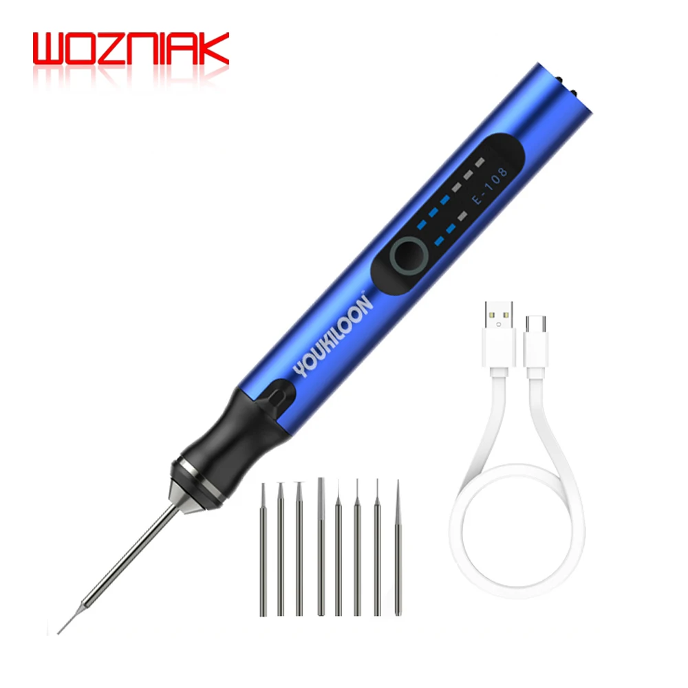
YOUKILOOM E-108 ntelligent Полировочная ручка винт сверление лица ID решетка резка

JC C1 Умный ремонтный блок OLED-экрана для зарядки аккумулятора, активации платы и линии питания для iPhone 8P 8G 7P 7G 6SP 6S 6G 6P.
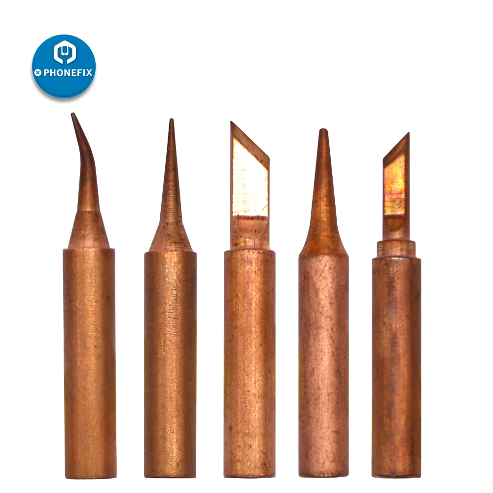
Паяльная станция для Hakko 936 Saike 909D 852D + 952D 900M-T наконечник пайки из чистой меди
257.48

Аппарат для вакуумного ламинирования Оса 15 дюймов TBK-308A восстановление
78275.56

Очиститель воздуха с системой центрального отопления, контроллером, фильтром, вентилятором, свежей системой, сенсорами температуры и влажности, катушкой и теплообменником.
31497.02
Характеристики
Analyze network vector tester handheld RF multimeter KC901Q 20GHz without built-in bridge sweeper sweep generator | Инструменты
Описание товара
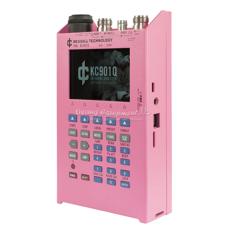
Analyze network vector tester handheld RF multimeter KC901Q 20GHz without built-in bridge sweeper sweep generator
![KC 901Q (1)]()
![KC 901Q (2)]()
![KC 901Q (3)]()
![KC 901Q (4)]()
![KC 901Q (5)]()
![KC 901Q (6)]()
![KC 901Q details (1)]()
![KC 901Q details (2)]()
![KC 901Q details (3)]()
![KC 901Q(7)]()
Introduction:
The KC901Q is a vector sweeper. He is able to measure the amplitude and phase changes that occur after the signal passes through the device, while extending the spectrum, field strength, and signal generator functions, adding practicality to form a RF multimeter.
The KC901Q uses the basic architecture of the KC901x. However, the KC901Q does not have a built-in bridge. The basic function is the sweeper (providing amplitude and phase), which is significantly different from other instruments in the KC901 series.
The KC901Q can perform vector reflection measurements with an external bridge or directional coupler. The instrument has a built-in full-port calibration model that supports OSL calibration. Sweep measurements support response calibration (amplitude and phase).
◆Main Features*
20GHz frequency range
1Hz frequency stepping
Good accuracy and stability
Double frequency conversion, strong anti-interference ability
Rich in function and easy to carry
◆Main function
Sweep test (get amplitude difference, phase difference)
Reflection test (external directional coupler required)
Low frequency and RF signal sources**
Spectrum display and field strength obser
◆Recommended application
The KC901Q is mainly used to debug various RF circuits, such as filters, amplifiers, splitters, combiners, external directional couplers or standing wave bridges, to test the input and output impedance, and to evaluate the quality of the antenna system. With its receiver, it can also detect the signal amplitude of each level of the equipment, and perform field strength measurement and interference search in some frequency bands.
KC901Q is a good tool for learning RF knowledge. In the professional field, it can be used in the fields of communication engineering, antenna manufacturing, and routine maintenance such as radar, microwave stations, satellite earth stations, and radio astronomy stations.
The following scenarios may not apply:
The spectrum and field strength functions are not suitable for measuring pulse and wideband signals (eg radar, WIFI, Bluetooth), frequency hopping signals. In some cases, qualitative observations can be completed by experienced engineers, but we cannot guarantee that every user can complete it.
Any test should not have strong interfering signals in the 109-110MHz range. Some broadcast transmitting stations have 109MHz spurs. If the antenna is measured near the transmitting station, it will affect the accuracy of the instrument.
◆Working principle
The basic principle of the KC901Q is similar to other products in the KC901x family, but it does not have a built-in bridge.
The basic principle of the instrument is that the RF signal source produces a measurement signal, which is sampled from the instrument 1 port after being sampled by the forward splitter. After the measurement signal passes through the device under test, it is input from the instrument 2 port, detected by the receiver, and compared with the signal sample obtained from the 1 port.
The signal source is divided into three frequency bands: signals below 60MHz are generated by a direct digital synthesizer (DDS); signals above 60MHz and below 7GHz are generated by a phase-locked loop frequency synthesizer
(PLL) and passed through an attenuator; The signal is multiplied and does not pass through the attenuator. The signals of the three frequency bands are gated through the RF switch and combined into one RF signal output.
The figure below is a block diagram of the KC901Q. The machine has two phase-locked loop frequency synthesizers with frequency dividers covering the range of 60MHz-15GHz. The circuit can work normally to 26.5 GHz until 30 GHz still has a weak output, but above 24 GHz, the indicator has rapidly deteriorated.
There are two receivers inside the instrument, and the local oscillator is provided by the same phase-locked loop frequency synthesizer. One of the receivers detects the output signal of port 1 through the internal circuitry of the instrument. The other receiver is connected to port 2 to detect external inputs. By comparing the amplitude and phase of the two receivers, the amplitude difference and phase difference between Port 1 and Port 2 can be obtained.
The instrument uses 7GHz as the breakpoint. Below 7GHz, the signal does not pass through the frequency multiplier and is output through the adjustable attenuator. The PLL outputs a signal of 3.5 GHz to 15 GHz, and a signal of 7-30 GHz is obtained by a frequency multiplier. Since the adjustable attenuator supporting 30 GHz is slightly more expensive, the application requirements of the integrated trade-off products have no built-in attenuators at frequencies above 7 GHz.
KC901Q uses secondary frequency conversion, the first intermediate frequency is 109.65MHz, and the second intermediate frequency is 350KHz. The second intermediate frequency is digitized by the synchronous sampling ADC and sent to the FPGA for subsequent digital processing.
The DDS in the machine can be directly output to form an audio signal source.
Since the KC901Q does not have a built-in bridge, an external directional device is required to measure the reflection parameters. An equal arm or unequal arm Wheatstone bridge can be used in the lower frequency band, and a directional coupler is preferred in the higher frequency band. Directional couplers can be made or purchased based on common frequency ranges. This type of coupler is inexpensive and reduces the cost of the package. The connection between the directional coupler and the instrument should be as short as possible, preferably with a semi-steel wire connection of no more than 20 cm in length.
The KC901Q does not have S11 factory calibration data due to the absence of a built-in bridge. After the external directional bridge is attached, calibration must be performed. If a bridge or coupler is often used, system calibration can be done for them for future use. If it is only a temporary measure, only user calibration can be performed. A disadvantage of user calibration is that once the frequency is changed, the calibration fails.
◆Technical specifications The basic technical specifications of the 901Q are as follows (the products may be slightly different in different periods): project Test Conditions parameter Remarks lowest typical highest Frequency Range Spectrum/transmission Effective 9kHz 20GHz Settable 0 30GHz Frequency Range (reflection) Effective Depending on the external orientation device in the 5kHz-20GHz range Settable 5kHz 30GHz Scanning range SPAN 1KHz 29.99GHz Scan points 450pt 3150pt Local operation Frequency resolution All scanning functions 1Hz Low frequency signal source 0.1Hz Level resolution 0.01dB Phase resolution 0.01° Scanning speed RBW=30KHz, every point 1.2ms RBW=10KHz, every point 1.5ms RBW=3KHz, every point 2.4ms RBW=1KHz, every point 4ms RBW=30K, 450pt per screen 0.6s Output level Scan mode 1MHz-7GHz -10dBm 6dBm 10dBm 7GHz-20GHz -13dBm 0dBm 6dBm 20GHz-26GHz -20dBm -13dBm -6dBm No guarantee Maximum output level 1MHz-7GHz signal source 3dBm 10dBm 13dBm 7GHz-20GHz signal source -13dBm 0dBm 6dBm Output attenuation 9kHz-7GHz 0dB 25dB Note 2 Sensitivity 1MHz-7GHz -101dBm -107dBm -113dBm Port 2 RBW=1KHz 7GHz-15GHz -98dBm -104dBm -110dBm 15GHz-22GHz -95dBm -101dBm The available dynamic range of the transmission measurement 1MHz-1GHz 95dB 100dB Equivalent to transceiver channel isolation Note 3 1GHz-2GHz 85dB 90dB 2GHz-15GHz 70dB 15GHz-24GHz 60dB 24GHz-26.5GHz 40dB Amplitude uncertainty of transmission measurement 1MHz-20GHz After straight-through calibration, when the insertion loss is L<40dB 0.5+0.1L Note 4 Zero offset drift of insertion loss When the existing insertion loss of compensation is L<30dB, 1MHz-15GHz 0.1dB Preheated for 5 minutes Directional device directivity is better than 15dB, directionality after calibration 9kHz-7GHz 45dB An external orientation device is required. 7GHz-15GHz 40dB 15GHz-20GHz 35dB 20GHz-26GHz 25dB


Трекер стоимости
Отзывы покупателей
Новые отзывы о товарах

Лиана 23 Декабря 2021, 17:19 #
Ещё в начале декабря заказывали ребенку игрушку миксер инженерный грузовик,пришел только вчера. Получилось как раз под новый год, подарок ребенку.... Читать отзыв полностью...


Арина 23 Декабря 2021, 17:58 #
Заказала себе сумку через сайт alisalebay.ru,заказом осталась довольна. Товар пришел через две недели. Такая же как и представляла,очень компактная,... Читать отзыв полностью...

Станислав 20 Декабря 2021, 07:39 #
Заказал себе данный Power Bank. Пришёл он мне в течении двух недель от момента заказа. При получении был надёжно упакован... Читать отзыв полностью...

Эдуард 23 Декабря 2021, 12:45 #
Отличный костюм! Сидит как надо. Очень хорошая ткань, в которой тело хорошо дышит, а не преет. Качественно прошитый у меня... Читать отзыв полностью...
Лиана 20 Декабря 2021, 14:07 #
Беру уже несколько раз с АлиЭкспресса ,через этот сайт. Очень довольна доставкой. Качество как всегда не подводило. Заказ приходит быстро... Читать отзыв полностью...

Второй раз заказываем с АлиЭкспресс, через этот сайт. Доставкой довольна,быстро и во время. На счёт халатов просто нет слов,заказали со... Читать отзыв полностью...